My O/S boots instantly
...but it just turns an LED on.
I've spent a few hours this afternoon on Baking Pi excercise OK1 for the Raspberry Pi.
The OK1 exercise results in an SD card with your own 'operating system' on it. In this case, it just turns on the OK LED on the rpi board, then goes into a busy loop.
The program is tiny (ignoring all the lines preceded by semicolons, they're just my comments):
.section .init
.globl _start
_start:

ldr r0,=0x20200000
;loads r0 with base address for GPIO
;GPIO has 52 pins only a few are avaialbe to us
;each pin gets 3 bits to determine what its doing
;so each group of 10 needs 30bits, or 4 bytes
;GPIO register is 6*4-24bytes total

mov r1,#1
lsl r1,#18
;load r1 with 1<<18,
;the address for the function select for pin 16
;(bits 18-20 of this bank of 10)
;the data here is 001, which sets the pin for output
;(000 is input, other values mean other things)
;unclear to me if loading this value affects the other pins?
;are we setting all other pins in this bank to input?

str r1,[r0,#4]
;put r1 into address r0+4,
;addressing the 2nd group of 10 GPIO pins
;pin 16 now ready for output

mov r1,#1
lsl r1,#16
;indicate which pin we're addressing, pin 16
;so this is a bitfield? can control many pins at once?

str r1,[r0,#40]
;r0+40 is address for turn pin (the data given) off,

loop$:
b loop$   ;loop forever
His instructions are clear; setting up the mac with the gnu toolchain was quick, and using his template file to create the assembler main.s was straightforward. All that could be done in about 15mins; the other hours I've spent are in trying to understand what's happening, flipping over the reference manual, following up on Wikipedia.
Most of that time was spent trying to work out what's going on with the GPIO register; the base address, the offset to target the relevant pin (the one wired to the OK led), the data that gets put into the offset to set it to output mode, then sending the index of the pin to the address for setting pins off (thereby turning the LED on).
There's a bit of jumping around between decimal and hex and binary, which is confusing. And because we're dealing with the CPU, the distinction between address and data is not completely clear. That is, the data in this register is the address for that operation, and populating that address with this data actually does something-- changes a pin state, lights an LED.
It's so easy to learn things as needed now -- when I was first learning about computers in the 70s, it was pretty impossible.
Some interesting things:
- kernel.img is 32 bytes
- the rpi needs a fat32 sd card with 4 files
- start.elf (which is the GPU image, a 2Mb binary blob)
- bootcode.bin, the 2nd stage bootloader
- kernel.img, the program that gets run
- config.txt, for options passed to kernel.img
- kernel.list and kernel.map generated by the compiler show your program and how it's laid out in memory
I remember reading about the MITS Altair and the IMSAI 8080 in Popular Electronics in the mid 70s.
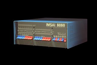
They were the first hobbyist computers, programmed by flicking switches on the front panel. No long term storage, tiny memory, and I/O limited to buttons and LEDs. From this limited start people would interface with keyboards and screens, write drivers for paper tape or cassette storage, and the basic assemblers and editors to increase capability enough to do the next round of pulling themselves up by their bootstraps.
The rpi is a completely different beast of course, with built in USB, HDMI, Ethernet-- many layers of complexity on top of the core CPU; none of which I have a clue how to access. Yet.
Now to make the LED blink.
Tags: raspberrypi
